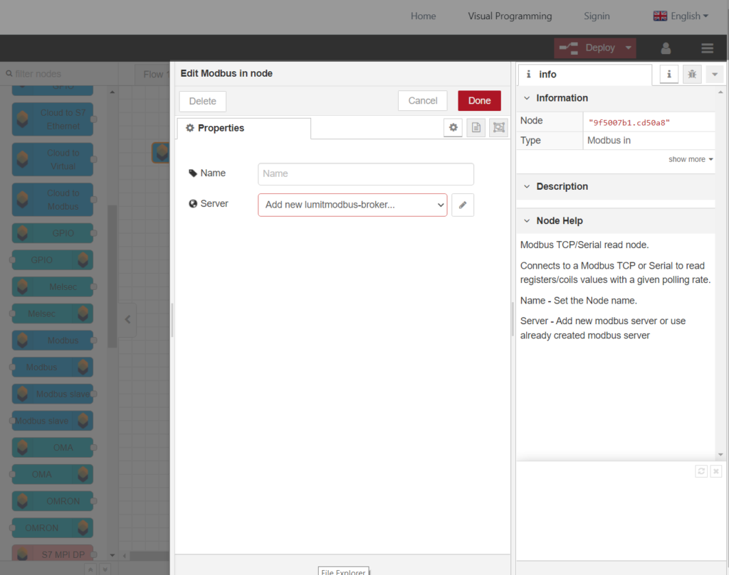
Step 1. Create Modbus Slave Node
| 1 | Set node name |
| 2 | Add new lumitiomodbus-broker |
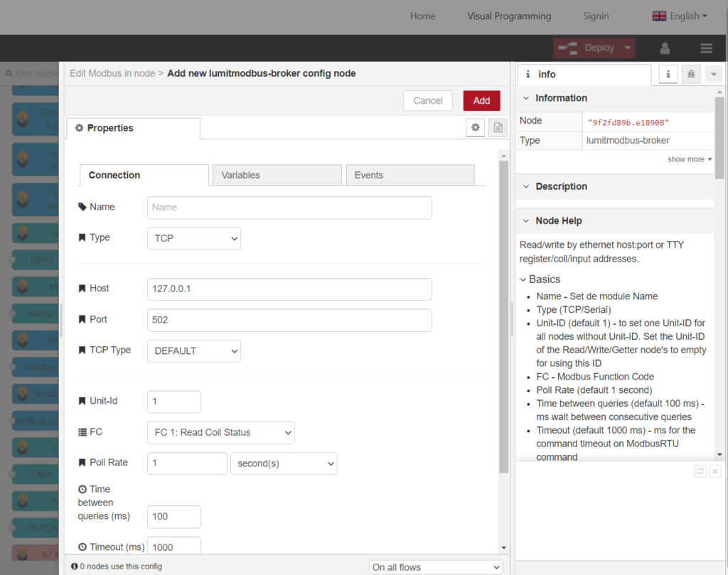
Step 2. Configure Modbus Slave Connection
| Name | Set the module name |
| Type | Serial Basic: Serial Port – /dev/ttyS2 Correspond to X30 COM or /dev/ttyS3 Correspond to X31 COM Serial type – RTU or ASCII Serial Baud rate – default 9600 Serial Expert: Databits Stopbits Parity Connection delay – time to delay first command sending after reconnect TCP: Host – IP address Port – default 502 |
| Unit-ID | default 1 |
| FC | Modbus Function Code |
| Poll rate | Default 1 second |
| Time between queries | ms wait between consecutive queries |
| Timeout | ms for the command timeout on ModbusRTU command |
| Reconnect timeout | Time to wait on reconnect before next sending |
Tip: If you are using Modbus Slave over TCP, you must set on the Host field the IP of the Ethernet port will be used on the Modbus bus.
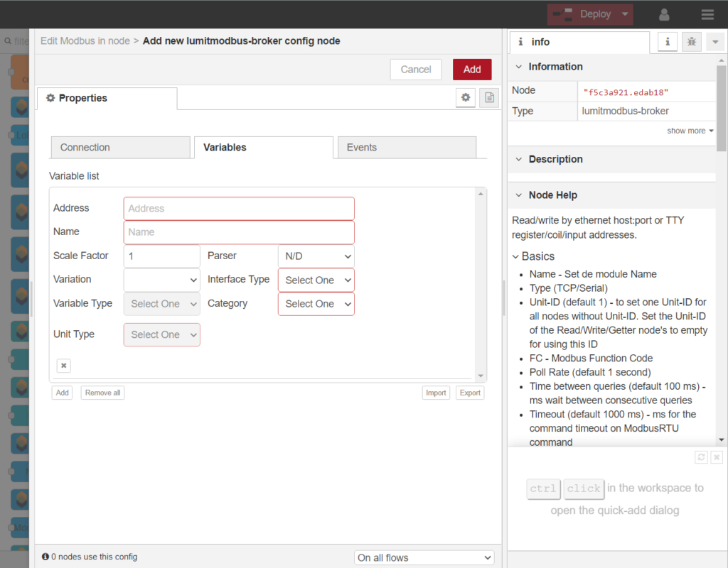
Step 3. Add Variables
| Address | Variable addresses format:<data type><byte offset>Supported data types: REAL – signed float INT – signed 16-bit integer DINT – signed 32-bit integer UREAL – unsigned float UINT – unsigned 32-bit integer X – binary Address examples: REAL0 – Read a single real value in offset 0 INT12 – Read a single integer value in offset 12 X12 – Read a single binary value in offset 12 |
| Name | Variable Name |