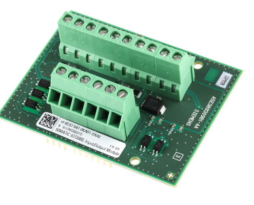
The following figure shows the configuration and interfaces of the IOT2000 Input/Output
Module.
Please read manual, before using this Node.
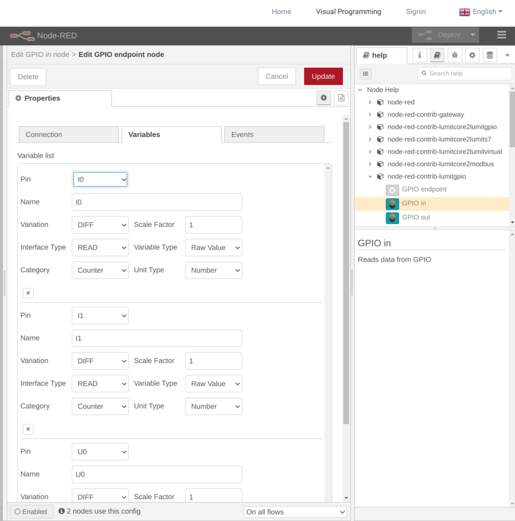
Step 1. Create GPIO node
| GPIO | Create GPIO endpoint |
| Name | Set node name |

Step 2. Configure GPIO node
| Interval | Pooling rate |
| Name | set GPIO endpoint name |

Step 3. Add Variable
| Pin | Choose: Digital Inputs: DI0 DI1 DI2 DI3 DI4 Digital Outputs: DQ0 DQ1 0-10V Analog Input: U0 U1 0-20mA Analog Input: IO I1 |
| Name | Set Variable name |