Compact server for private LoRaWAN networks, that integrates both the network-server and the application-server. This is useful for application providers that operate their own LoRaWAN network, or for device and application developers.
Lumit.io pre-configure the server for the EU868 region, you only need to add devices.
Step 1. Open your browser and type the equipment IP address: http://192.168.200.1:8080
The default access credentials:
| Username | admin |
| Password | admin |
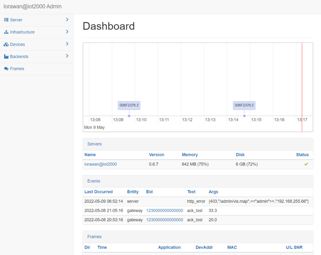
Step 2. Dashboard
Overview of the LoaraWan network.
Last Occurred Events.
Last LoraWan Frames.
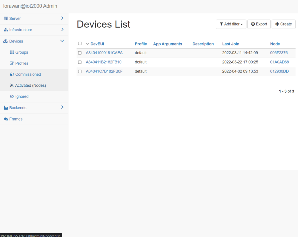
Step 3. Add Devices
Got to Devices/Commisioned tab.
This list contains devices that can join the LoRaWAN network using the over-the-air activation (OTAA).
Step 4. Click in create
| DevEUI | DevEUI of the device. |
| Profile | Use Default |
| AppArguments | is an opaque string with application-specific settings. |
| AppEUI | Device AppEUI |
| AppKey | Device AppKey |
| Description | For your convenience |
| Last Joins | Is a lost of timestamps of the previous successful Join requests. |
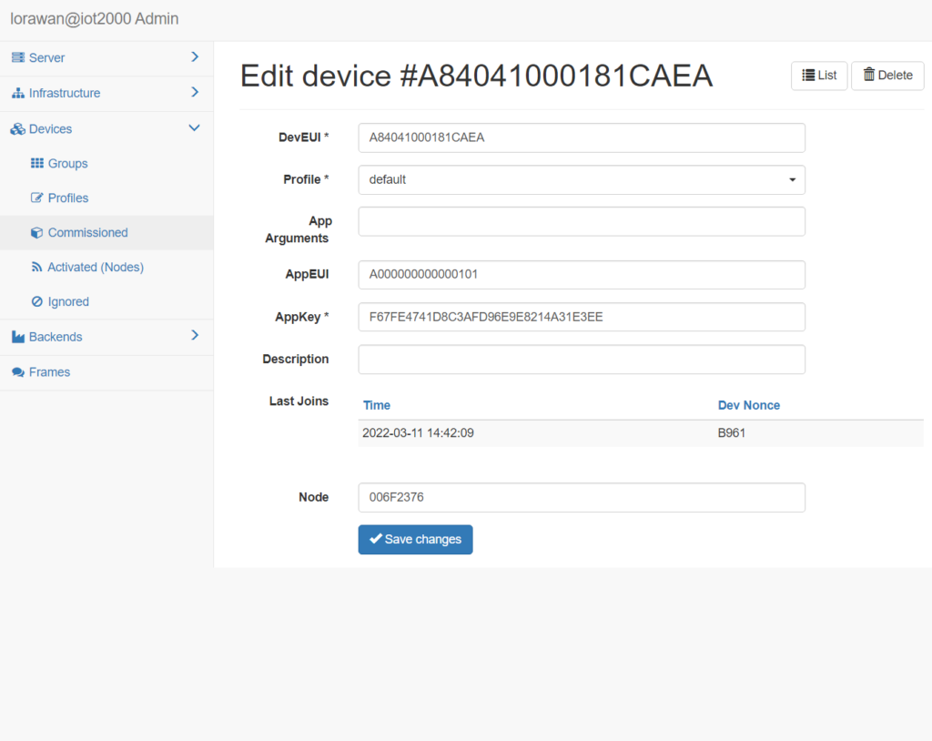
Note: Once the device joins the network, the Node field will contain a reference to the Nodes list.
Step 5. Activated (Nodes)
This list contains active network nodes that either have already joined the network using the over-the-air activation (OTAA) or have been activated-by-personalization (ABP).
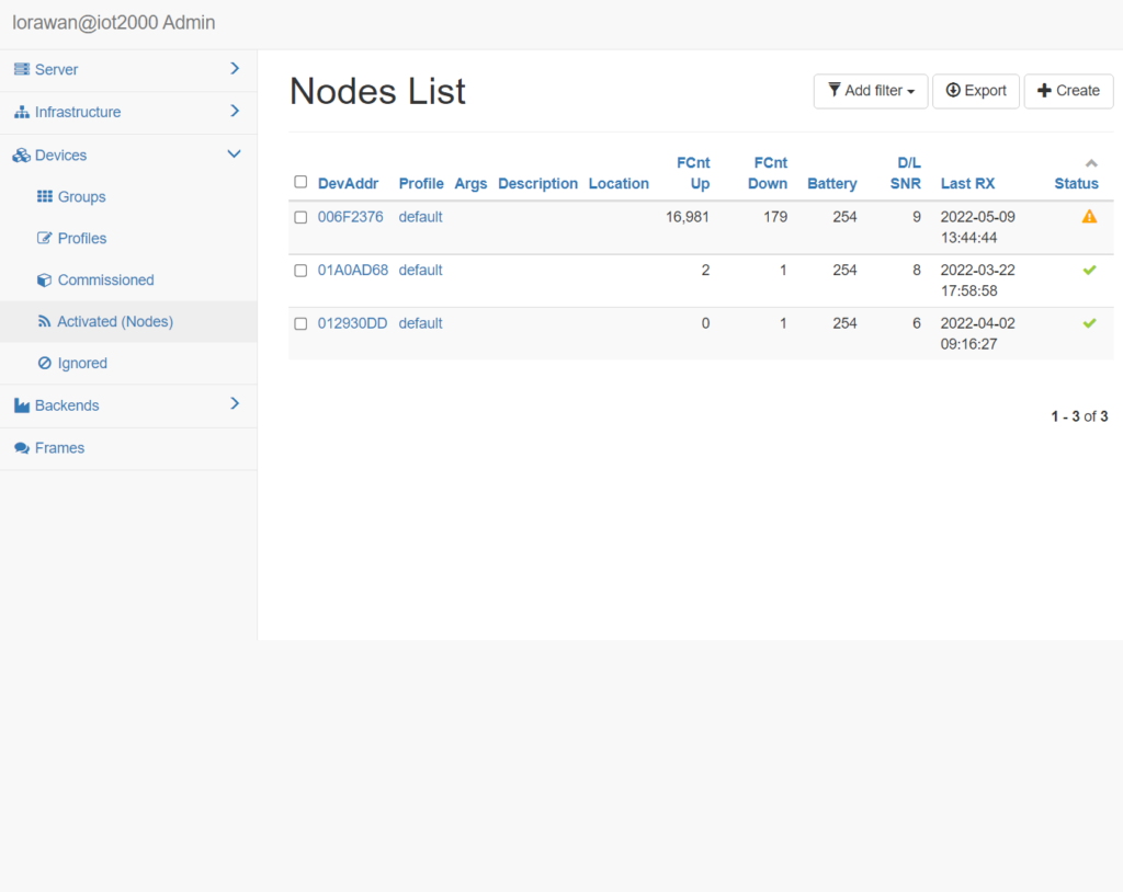
Step 6. Check active node status
For each active network Node you can set:
| DevAddr | DevAddr of the node. |
| Profile | Profile that this Node uses. |
| Location | user-defined string |
| NwkSKey and AppSKey. | LoraWan Keys |
| FCnt Up and FCnt Down | frame counters |
| Last Reset | Indicates time of the last Join or reset. |
| Last RX | Indicates time of the last uplink frame |
| Device | Shows a link to a corresponding Commissioned device. |
| Gateways | Gateways that received the last uplink frame. |
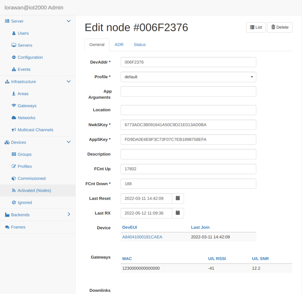
The Downlinks table contains frames created by the application, which are scheduled for transmission. Class A devices listen for downlinks only for 2 seconds after an uplink transmission, so it may take a while until all messages are transmitted. Class C downlinks are not listed there as these are scheduled immediately.
Each Node follows the ADR Mode defined in the Device Profile (see above). The Node ADR parameters include:
| ADR Support | Indicates the node can do ADR |
| Set Power | defines the power (in dBm) |
| Set Data Rate | Define the data rate |
| Set Channels | Defines the set of channels. The channels are given as a comma-separated list of interfaces, e.g. 0-2 (for EU), 0-71 (for US), or 0-7,64 (for the first US sub-band). |
| Used Channels | Indicates the set of channels used |
| ADR Failed | Flag will indicate the device refused the last ADR command. The user is expected to resolve and clear this field before ADR will continue |
| Used Duty Cycle | Number 0-15, where 0 means no restrictions |
| Used RX1 DR Offset | Indicates the offset used; |
| Used RX2 DR | Indicates the RX2 data rate used; |
| Used RX2 Freq | Indicates the RX2 frequency used (in MHz); |
| RX Change Failed | Flag will indicate the device refused the last command. |
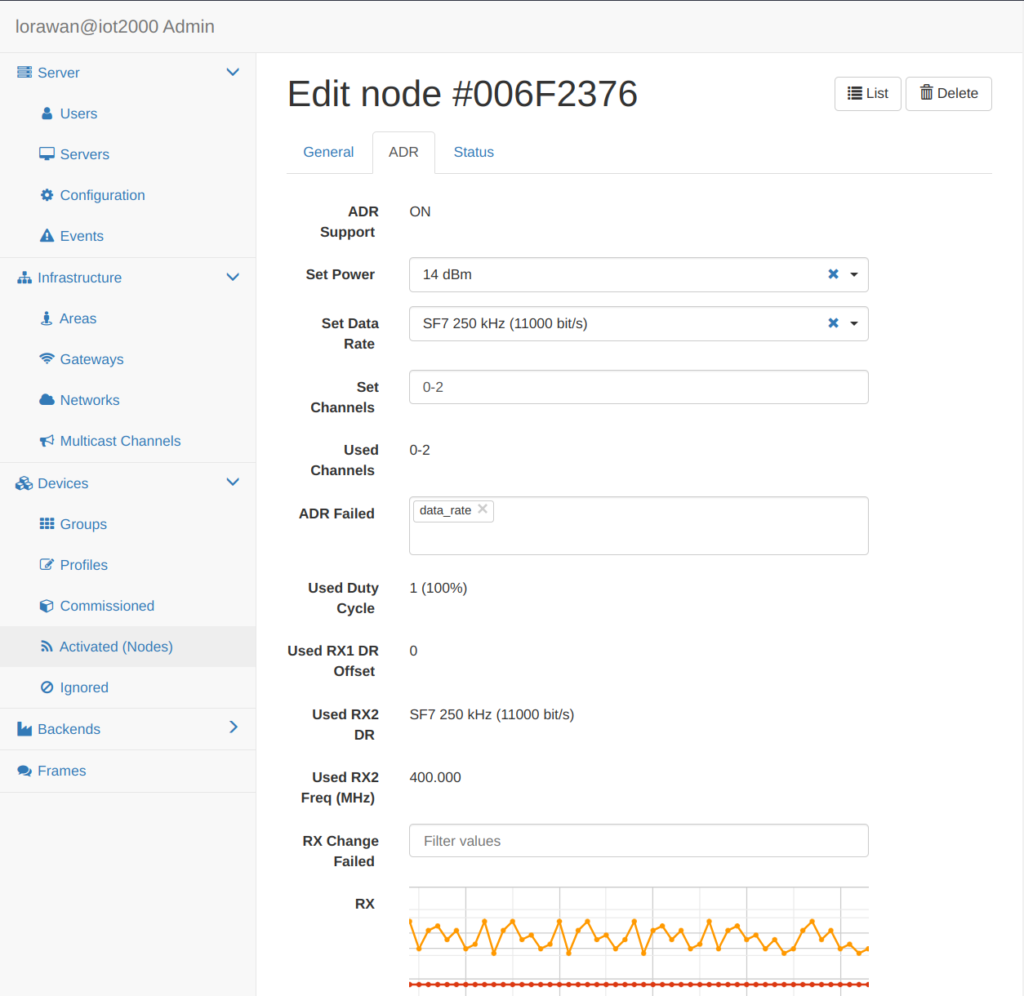
Below the configuration options you can monitor the performance of the node. You can see the assumed ADR parameters and two graphs that display the last 50 received frames.
| Rx | Graph indicates the device Power (dBm), Data Rate and Frequency (MHz); |
| RX Quality | Graph indicates the SNR (dB) and RSSI (dBm). |
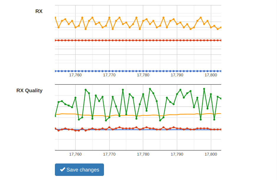
Note: that the (Google) graphs will not be displayed when the Internet connectivity is not available, e.g. in an isolated network.
This tab shows:
| Alert | battery_low – battery below 20%. downlink_noise – when the indicated D/L SNR is close to the sensitivity limit. many_resets – when the device sent multiple Join requests without sending any other frames. |
| Status | Last received by the server |
| Device Status | graph that shows the recent device Battery level (0-255) and the Signal-to-Noise-Ratio of received downlinks (D/L SNR). |
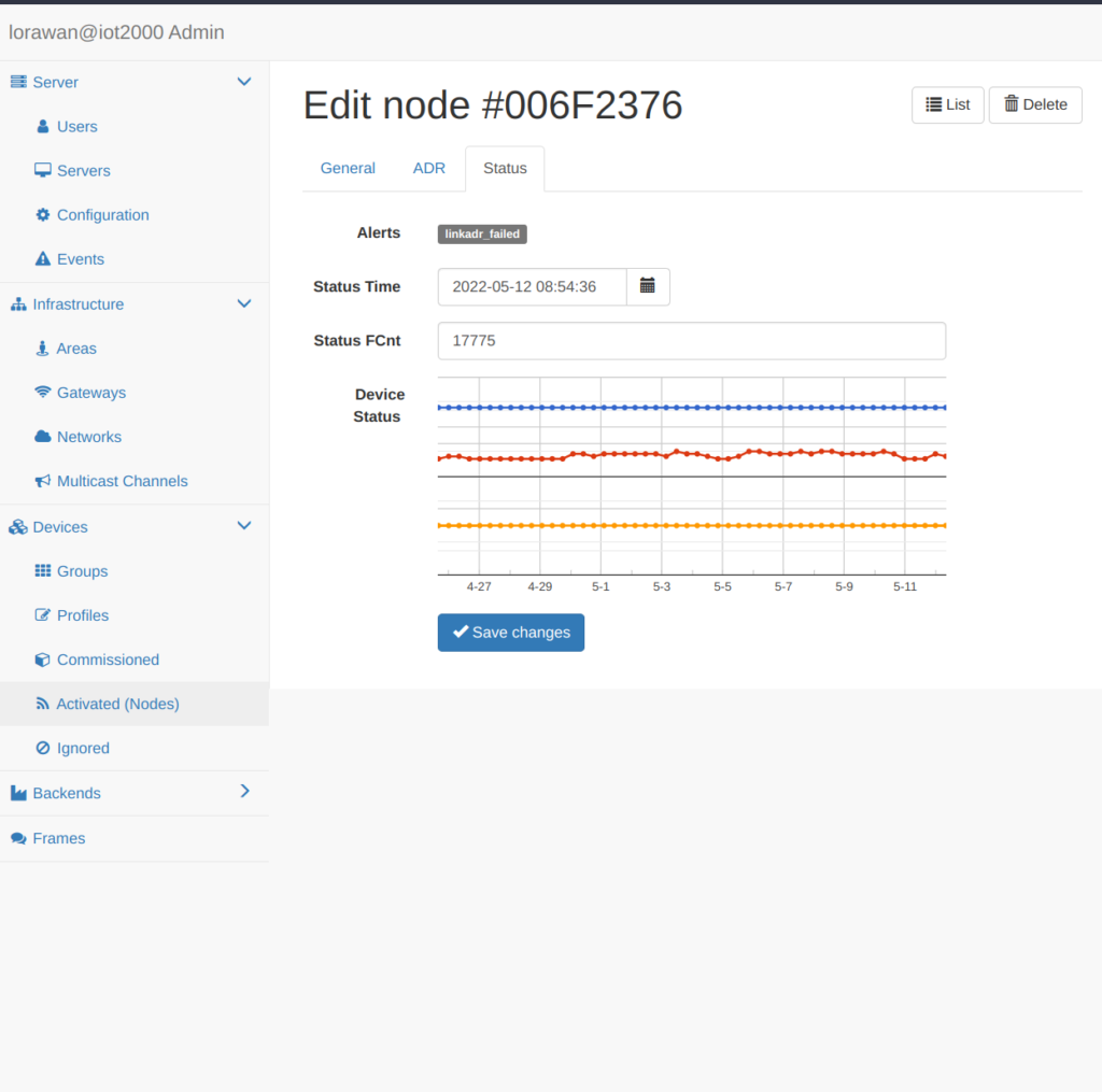
The server requests the device status upon join or reset and then at given time/fcnt intervals defined by the devstat_gap parameter. By default {devstat_gap, {432000, 96}}, which requests the status every 5 days or every 96 frames (whatever occurs first). The server also requests device status when the ADR parameters change.