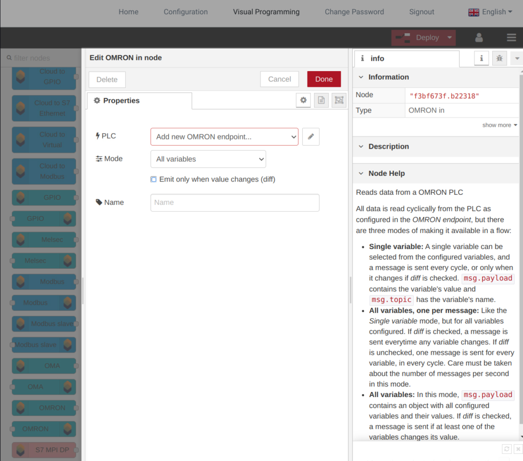
Step 1. Create Omron node
| 1 | Set node name |
| 2 | Add new lumitiomodbus-broker |
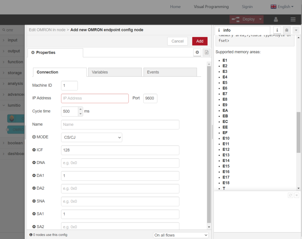
Step 2. Configure Omron Connection
| 1 | Machine ID |
| 2 | IP Address and Port |
| 3 | ICF – Information Control Field DNA – Destination Network Address: Enter 0 for “this network”, 0x1~0x7f for remote DA1 – Destination Node: Enter 0 for “this node”. Often this is set to the value of the last octect of the PLCs IP Address. Ultimately, if none zero, it should match the node number set on the PLC. DA2 – Destination Unit: Enter 0 for CPU, 10 to 1F for CPU BUS Unit (10+Unit), E1 for inner board SNA – Source Network Address: Enter 0 for “this network”, 0x1~0x7f for remote. Check the PLC Netowrk Routing table. SA1 – Source Node: For direct communication, try entering 0 or setting it to the value of last octect of node-red IP Address. Depending on the network subnet mask and the FINS conversion method setting, it may be necessary to enter the node-red IP and Node Address number in the PLC FINS/UDP IP Address Table SA2 – Source Unit: Enter 0 for CPU, 10 to 1F for CPU BUS Unit (10+Unit), E1 for inner board |
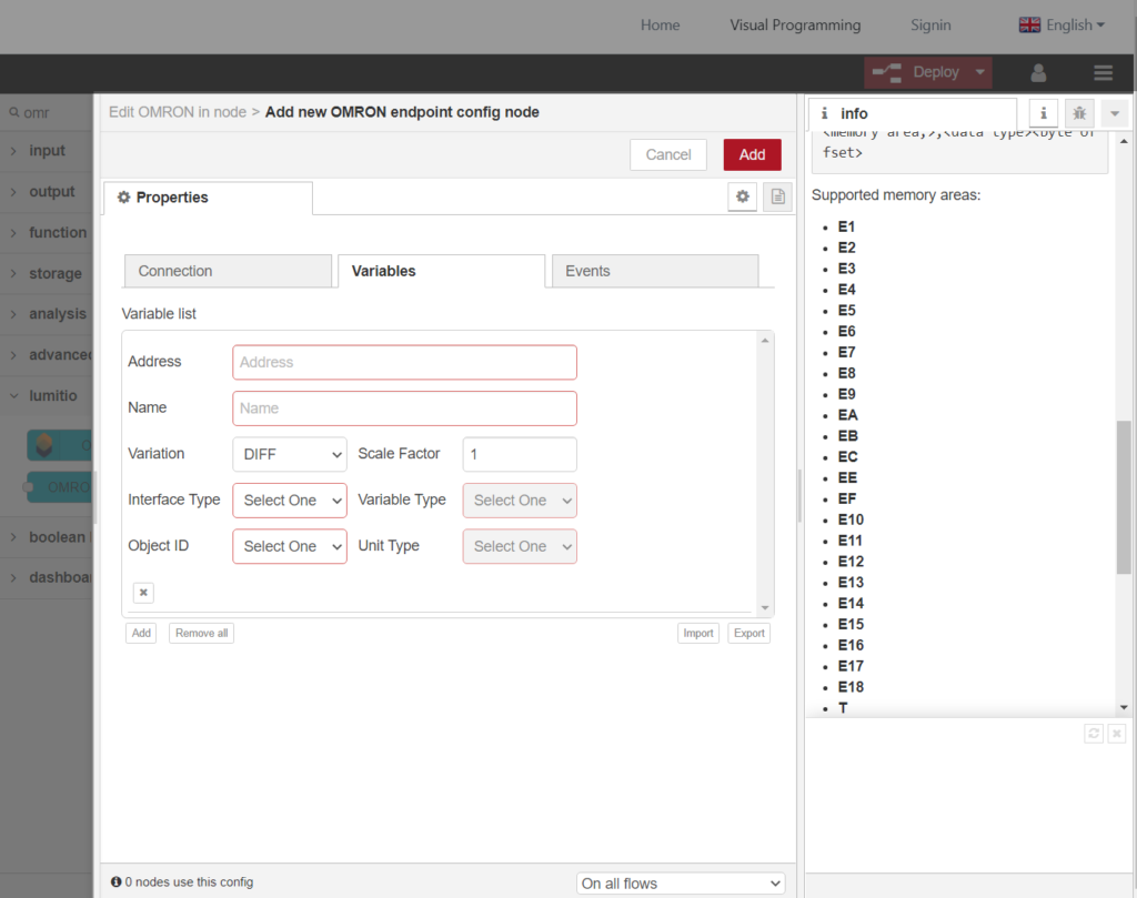
Step 3. Add Variables
| Address | Variable addresses format:<memory area>,<data tye><byte offset>Supported memory areas: E1 E2 E3 E4 E5 E6 E7 E8 E9 EA EB EC EE EF E10 E11 E12 E13 E14 E15 E16 E17 E18 T C CIO W H A D IR DR Supported data types: REAL INT UINT BOOL Address examples: D,REAL00651 – Read in offset 00651 from D. D,INT00650 – Read in offset 00650 from D. |
| Name | Variable Name |